 (3)
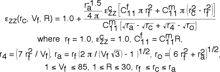
(3)The second example is an analytic function but unlike the first analytic function, eqn. (1), there is a physical basis for this function, hence, there is an opportunity to relate our function to the geometry and physics of this particular problem. This function is given below where the strain, εzz, is a function of the crack radius, rc, fiber volume fraction, Vf, and elastic property ratio, R, taken from a report Ref.[1] written by Carman, Lesko, and Reifsnider.
(3)
The function given above is derived from the boundary value problem shown below in Fig. 13, where the unidirectional fiber-reinforced composite sustains a crack in the center fiber of a composite subject to a prescribed remote strain and the crack grows towards the adjacent fibers. The strains at the interface of the adjacent fibers are identical due to symmetry and these strains should increase with increasing crack growth. The effect of increasing fiber volume fraction and elastic property ratio on the interface strain is less obvious, but the physics would suggest an increasing strain with increasing fiber volume fraction and elastic property ratio. As before with eqn. (1), trends can not be deduced from eqn. (3) because the complexity of the analytic function does not suggest a possible trend, "it goes like". Here our objective is to better understand the relationship between interfacial strains over a range of parameters that can be physically controlled during fabrication of this composite material system. Hence like the previous experimental data set we are also interested in choosing from a range of possible parameters where this selection process results in a well designed composite material system. Again this selection process can best be accomplished using the compressed-interactive-comparative format.
Figure 13. Physical parameters defined for fiber fracture model.
Again we avoid using the family-of-curves format and immediately construct the function in the comparative-interactive-compressed format as shown in Fig. 14. Before moving any planes, we observe the highest strain appears in the lower left corner where R=1, rc = ra, and Vf.
Figure 14. Interfacial strain relationship with material parameters.
As in the previous examples the horizontal rc - Vf plane is the initial plane of interest but as shown in Fig. 15 movement of this plane reveals little new information. In Fig. 16, the strain variations observed in the rc - R plane reveal a minimum strain over a large range of fiber volume fractions. But in Fig. 17 we observe a minimum strain only for the larger crack lengths. In these figures we observe that for a given crack length we can choose an optimum fiber volume fraction and elastic property ratio that will minimize the interfacial strain at the unbroken neighboring fibers. Note that both the fiber volume fraction and elastic property ratio can be controlled by the material engineer who is designing this material system. Hence we can use this visual method to optimize the fabrication of a material system for a given property: in this example we have minimized the strain to failure of adjacent fibers. Of course the same result could have been obtained by using a variational analytic method, but only if the function is differentiable. In some cases a numerical method is appropriate when an analytic approach is impossible. In either case it may be desirable to first observe in a comparative format which parameters are the best candidates for optimization. Again we find that by using a visual comparative method first, we can more efficiently use numerical, analytical or experimental methods which are better at providing quantitative information. Hence visual methods complement existing methods.
Figure 15. Variation in interfacial strain in the rc - Vf plane at various values for R.
Figure 16. Variation in interfacial strain in the rc - R plane at various values for Vf.

Figure 17. Variation in interfacial strain in the Vf - R plane at various values for rc.